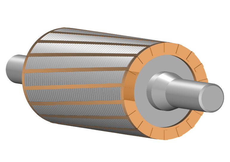
You cannot see a magnetic field, hold it or photograph it — but engineers still need to know exactly where it is strong, where it leaks and what it will do inside a motor. That is what finite element analysis (FEA) is for: a computer simulation that turns the invisible field into numbers and pictures.
What FEA actually does
The idea is simple. A magnetic field is continuous — it exists at infinitely many points. FEA slices the space into many small pieces (a "mesh"), calculates the field in each piece, then stitches the results together. More pieces mean better accuracy — and longer computing time. The output is usually a plot of flux lines, a map of field strength, and numbers you can read at any point.
Why simulate at all?
- Before you build. Testing designs with physical prototypes is slow and expensive; a simulation costs nothing but time.
- Try many variants. Change the magnet size, the steel shape or the air gap, and re-run — you see the effect in minutes.
- Find problems early. Leakage and weak spots show up on screen before they show up in a failed product.
The workflow in five steps
- Draw the geometry — the magnet, steel parts and surrounding air.
- Assign materials; a magnet also needs its magnetization direction.
- Build the mesh — finer where the field changes fast.
- Solve — the computer runs the math.
- Post-process — look at flux plots and read the numbers.
Common software
Popular tools include ANSYS, Comsol Multiphysics and JMAG — they all do the same job with different interfaces. The hard part is rarely the software; it is entering good material data. Garbage in, garbage out: a pretty picture means nothing if the inputs are wrong, so engineers always check the simulation against at least one measured value (see surface flux).
Read on: mechanical properties → · magnetic circuits →